One of my biggest complaints about the 2012 Boss Mustang is that the standard version came with only a tach and water temp gauge to monitor the engine. That’s fewer gauges than what was available on a Mustang GT. Hell, even my buddy’s 1975 Audi Fox had a three-gauge pack from the factory! The Laguna Seca took a stab at remedying this with a hideous dash-top pod containing gauges for oil pressure, water temperature, and…a G-meter. A G-meter? On a racetrack, that is about as useful as a compass.
The 2013 Boss has a TV in the dash with gauges that can be scrolled through one at a time or some other such nonsense that I can’t reproduce, even if I wanted to. Since I only need the added information while I am at the track, my ideal solution would be to upgrade my Aim Solo to a full Boss 302R-style AiM Dash that can be mounted on the steering column and then removed when the car is on the street. Unfortunately, I can’t see getting into one of those systems for less than two grand, so it will have to wait.

The Laguna Seca Gauge Pod (Ford press photo)
The best option for me was to upgrade to the Laguna Seca gauge pod. I think the car deserves better instrument integration than a pod screwed into the dash, but it’s functional and factory correct. The fully loaded kit lists for $1400, but since the biggest ticket item is the goofy G-Meter, I decided to buy the gauge pod separately (about $85) and choose my own gauges.
Innovate Gauges
The Ford Racing Gauge Pod accomodates three gauges in the industry standard 2 1/16″ size. The options for filling those spaces is almost limitless. If you want to be factory correct, AutoMeter makes the Ford Racing gauges as well as budget options and high-end programmable gauges with stepper motors and alarm modes. Normally, I would go for the analog gauges that most closely matched the interior of the car, but instrument technology has made Fast and Furious progress in recent years. The latest gauges feature multiple functions, LED lighting, and user programmability. Based on my limited but satisfactory experience with their Air/Fuel gauges, I chose Innovate Motorsports and their new MTX line of dual-function gauges. I decided on an oil pressure/temp gauge, a water temp and voltmeter, and an Air/Fuel gauge. This would give me five new data sources packed into a gauge pod intended for three.
Gauge and Gauge Pod Assembly
The Ford Racing Gauge Pod itself is nice enough I suppose. There is some flash on the bottom that needs to be trimmed off for it to sit flat and I also don’t like how the two outside gauges are only secured into one mounting tab. Of course it is sufficient. I just don’t like it.

I started to assemble the gauges into the gauge pod and that is when I first realized I had made a huge mistake. Okay, maybe it wasn’t a huge mistake, but as usual, I had definitely chosen a more difficult path. It turns out that the gauges I wanted to use were so innovative, that they chose to locate their mounting posts using a non-standard width. As you can see, the posts do not fit into the pre-drilled mounting holes.

Worse than that, the gauge bodies fit into the standard sized hole, but the gauge faces are larger than average. From a standpoint of readability, this is a good thing. But the larger faces and thick bezels make for fitment problems in tight spaces. These photos show the interference.


I figured that I had three options:
1. Punt. Return the gauges and exchange them for gauges known to fit. That’s quitter talk.
2. Use two of the Innovate gauges in the outside gauge pod locations and make a blank for the middle. This would be easy to do, probably look okay, and still give me four new data points. This is a good idea.
3. Make ’em fit. This would mean cutting and grinding on brand new, expensive gauges, possibly ruining them, and certainly terminating their warranty, all to try and fit a “fifth” gauge which I probably don’t even need. This is a dumb idea.
I decided to make ’em fit.
WARNING! For those following in my footsteps, as you will soon see, this is not for the faint of heart. You will need to grind on the bezel, the case, and even the circuit board of the gauge itself, mere millimeters from delicate circuit paths. One slip of your Dremel tool and you could ruin your $200 gauge. Innovate Motorsports will likely be sympathetic to your can-do attitude, but they are unlikely to accept the return of a willfully mutilated instrument.
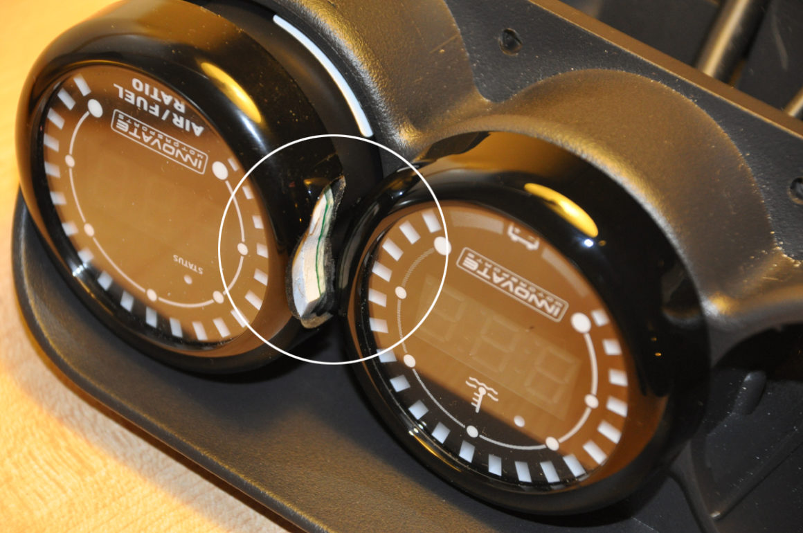
You can see here how much I had to grind off of the gauge to make it fit. I did not do this with an assembled gauge! I disassembled the gauge and modified each piece individually and by hand. I measured as much as I could and took my time. I made cardboard templates and I practiced on one of the spare bezels that come with each gauge.
I could have ground less from each gauge if I had taken material off of all three. But, I decided to leave the middle gauge wholly intact. For one, I liked the design idea better. Having the middle gauge whole with “crescent” gauges on each side is very similar to some Porsche instrument clusters. Also, I would only have to make two cuts, rather than four (introducing more chances for mistakes). Finally, at least one gauge remains intact, in case something goes horribly wrong and the gauges need to be re-purposed. To that point though, the modified gauges can be refitted with a new bezel and once installed, none would be the wiser that there had been any modifications to it. They would look as good as new.

Once the gauges fit flush, I used a thin piece of aluminum as a mounting bracket. This took the place of the built-in plastic ears that had to be drilled for these particular gauges. It also allowed the use of both mounting posts for each gauge. I added some insulation (not shown) between the wires and the aluminum strip to prevent abrasion that could cut the wires.
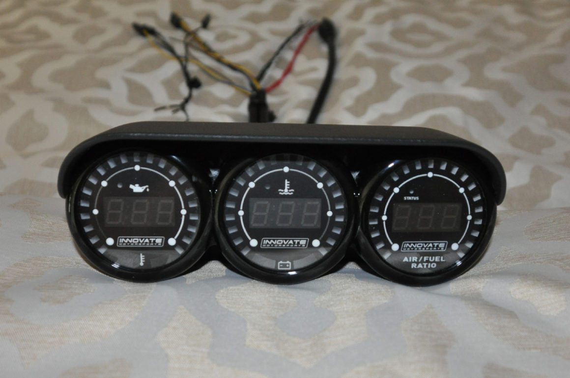
The modified gauges in the Ford Racing gauge pod.
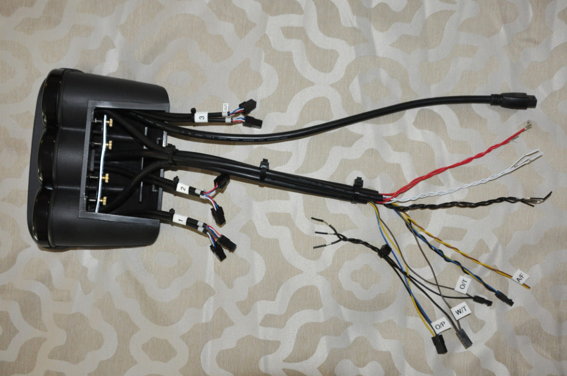
I assembled the gauge cluster and then organized the wiring harnesses with wire ties and labels.
Gauge Pod Installation
The rest of my instructions should be generic enough to apply to most installations. Wiring harnesses to the gauges will be different in some details (connector locations and such), but all will consist of the same basic wires: power, ground, light dimmer, and sensor signal(s). But first, it’s time to saw a hole in your new dash!
I’m lazy, so the first couple of instructions are just cut-and-pasted from another FAQ that I did.
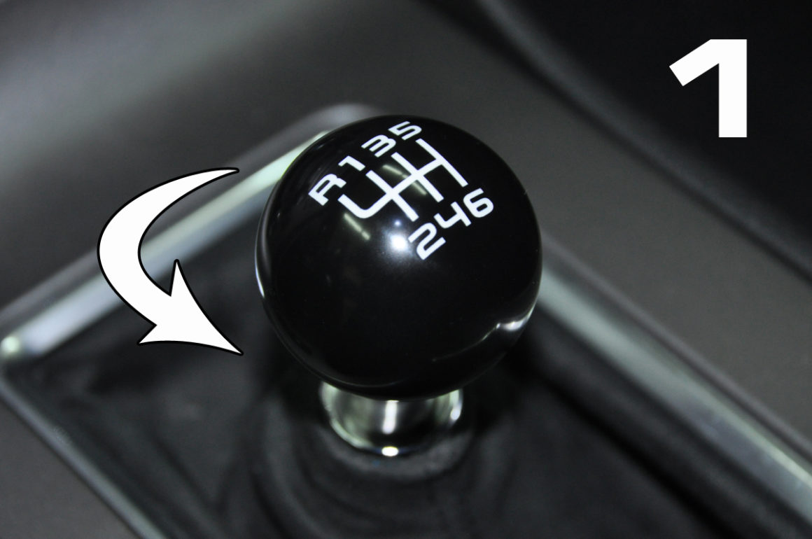
1. Remove the shift knob by rotating it counter-clockwise. But you need to know something about that shift knob, or you are likely to get a hernia. It’s held on with blue Loctite. That’s right, Ford fitted this car with a Chinese transmission made from the melted-down pots and pans of dead dissidents and it’s almost certainly destined to fall apart faster than a student protest. But by God they don’t want that shift knob falling off. No sir.
Check the forums for ideas on how to remove the shift knob. You might get a musclehead friend or somebody on PCP who doesn’t feel pain. You also might try applying heat to break the Loctite bond. A rubber-strap oil filter wrench might work, too. I’m not going to tell you what I did, but let’s just say that now I have to order a new shift knob.


2. Open the storage compartment and then pull the center console trim piece by pulling up here (Fig. 2). It will unclip easily. Slide the boot over the shift lever, unplug the traction control/hazard/trunk release connector and remove the trim piece.

3. Remove the two (2) 7 mm bolts that secure the HVAC/radio control panel.

4. Carefully pry the top corner of the panel and it will pop free.

5. Unplug the single connector and remove the panel.

6. Remove four (4) 7 mm bolts that secure the radio display. Also, clean the display, because it will be nasty. Finally, put a piece of masking tape across the opening of the CD player to prevent ingress of dust when cutting/drilling on the dash.

7. Use the gauge pod mounting bracket to make a cutting template. Measure and test-fit. Repeat.

8. Saw/drill/cut/grind a hole in your dash. I used a Dremel tool with a cutting wheel. Other people have used box cutters and drills with step-bits. A right-angle adapter for the drill would be ideal. The Dremel worked, but because of the thickness of the dash, the cut is at an angle. If I had to do it all over again, I would have used a drill.

9. I made my cuts in two parts. The first cuts cleared the soft part of the dash material. The second round of cuts went through the second layer of the dash, which is (thin) hard plastic. I finished-up with a grinder attachment on the Dremel to smooth the edges of the hole.

10. Route the wiring through mounting bracket and the dash. Do not mount the bracket yet! As well as you may have measured, it’s possible to have made a mistake while cutting in such an awkward location. I did. Tape the bracket in place on the dash, route the wiring, and fully seat the gauge pod onto the bracket. Check the final fitment. Small corrections can be made to the bracket location without re-cutting or drilling the hole for the wiring.

11. Once you are satisfied with the fitment, secure the bracket with the supplied screws. If you have a drill with a right-angle attachment, you will want to drill pilot holes to get through the hard plastic. With enough force, it is possible to get the supplied screws to bite into the plastic, or you can purchase self-tapping screws. Start with one screw and then check to make sure the bracket is square with the dash. Adjust the angle until it is square and then secure the bracket with the remaining screws.

12. Route all of the wiring through the dash, seat the gauge pod down on the bracket, and secure from the front with the two supplied screws. Take a break and admire how good your gauges look. They don’t do anything yet, but yeah, they look good.
Interior Wiring

13. To power the gauges, you will need access to the fusebox behind the passenger kick panel. Remove the kick panel by simply pulling on it. For even better visibility and access, I also removed the door jamb trim (Fig. 13). This is also removed by just pulling it free from the body. At the bottom, the lower door trim must be pulled-up first and then the door jamb trim will pull free. The fusebox is behind a paper cover held in place with Velcro.

14. Use a multimeter to find a switched ciruit and use a Bussman Add-a-Circuit for power to the gauges.

15. Route the wire along the harness that is already located behind the glove box.

16. I connected the power wires (RED) using quick-disconnects for easier removal and maintenance of the gauges in the future. I also prepared the dimmer wiring (WHITE) with a quick-disconnect. If I decide that I need a dimmer function, I will connect it to the fusebox in exactly the same way as I did the power (except using an appropriate dimmer circuit).
This is a also good photo of the Boss Mustang ring bearer pillow. I bet you didn’t know it came equipped with one of those, did you? Precious. Race car with a license plate? No wonder the Z-28 guys are going to laugh at us. They get dry sumps and we get extra pillows.
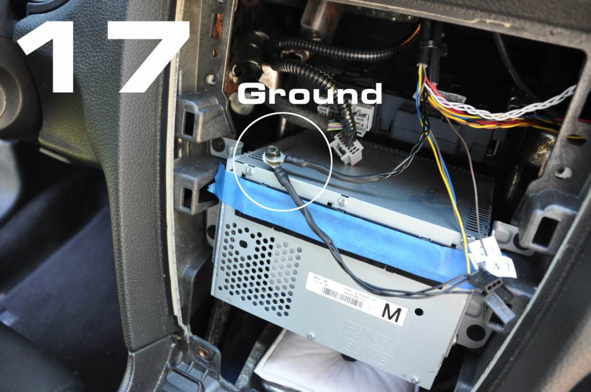
17. The Innovate gauges came with two sets of grounds: one set for the gauges and one set for the sensors. The instructions said they were to be grounded in the same place. I crimped each set to ring connectors.

18. I found a good ground location on the metal frame that holds the HVAC and radio modules. There was already a hole, so no drilling required. I just found a nut and bolt that would fit.
Sharp eyes will notice that my continuity girl was asleep at the wheel and these photos were published out of order. I actually did the ground wires first and then the power. No matter, the instructions are correct and the wiring can be done in any order.

My continuity girl. She also helps me with the fine print, since my old eyes aren’t so good anymore. Here she checks to see if the quick-disconnects are correct for the gauge of wire that I am using.
Exterior Sensor Wiring
The Voltmeter works just by being powered by the car’s electrical system. No other wiring is necessary.
For the Oil Temp and Oil Pressure sensors, I used a sandwich plate adapter (M22 x 1.5) from Prosport Performance. The adapter fits between the engine block and oil filter and has four 1/8″ NPT ports for adding sensors. It’s also Kona Blue, so I couldn’t resist.

19. Install the oil temp and oil pressure sensors, before installing the sandwich plate adapter. Be sure to use Teflon tape or other proper thread sealant to ensure that there are no leaks.
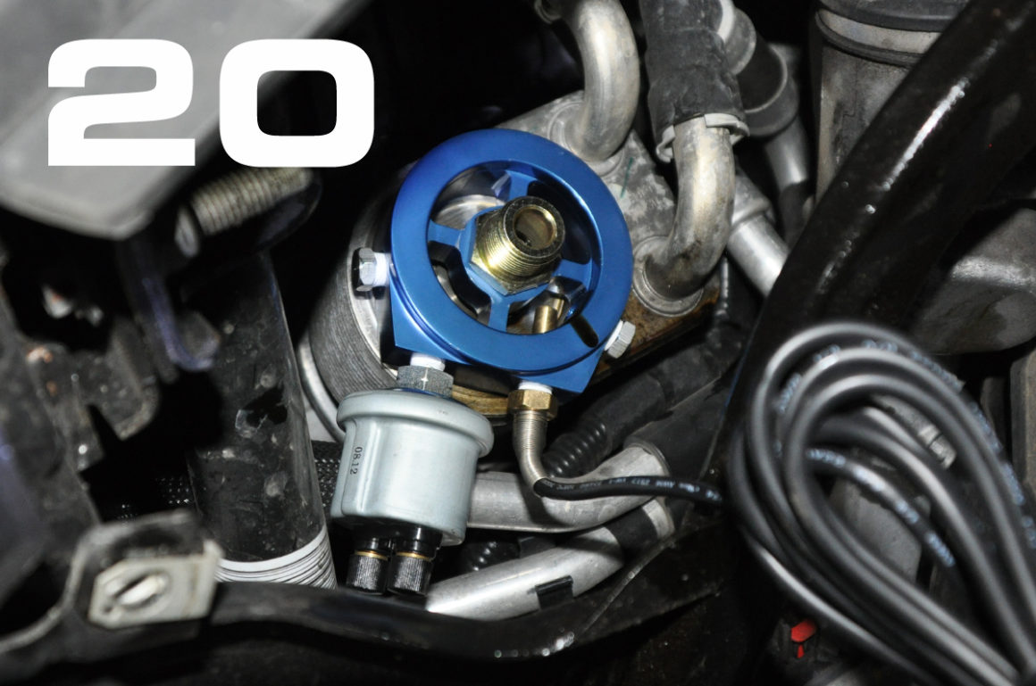
20. Install sandwich plate adapter by lowering the oil filter service cover (8 mm bolts x 3) and removing the oil filter. Follow the instructions that come with the sandwich adapter. Reinstall oil filter and tighten by hand. Attach wiring to sensor leads and route the wires to the firewall. Close oil filter service cover and tighten bolts.

21. I covered the wires in a plastic sheath and routed them up and across towards the firewall, as seen in the photo. I used an open space in a factory guide to secure the harness.
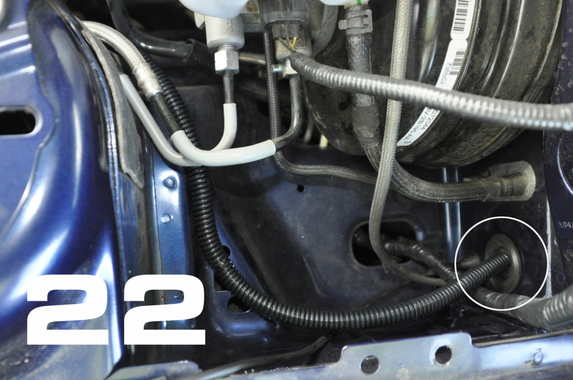
22. Route the harness into the cabin. I went through an opening in the firewall previously used for the sound tube.
23. (no photo) Route wiring under the dash and connect to gauge harness. Be careful to route the wiring in such a way that it does not interfere with any pedal or steering operation!
Programming the gauges
A laptop can be used to program the gauges. The programming software, serial cable, and instructions are supplied.
There isn’t much to adjust on the oil pressure gauge. I set the alarm to trip at 10 psi of oil pressure or less.
There is a bit more flexibility with the oil temp gauge. I set the low (green) range to be anywhere from cold to warm. I know that on my ordinary commute, which involves highway speeds in 6th gear, the oil will get warm, but will not advance to the middle range, unless I use a lower gear (higher revs) too often. I set the middle range (orange) to be the normal/advanced range. Using high revs and certainly any kind of track driving will put the oil into this range. I set the high range (red) at 250 F and set the alarm to trip at 280 F, which is the limit of the gauge.
Test Drive
This video shows the gauge at startup and during ordinary highway driving in 6th gear at 65 mph. Then I show what happens when you drive at 65 mph in 4th gear. Just the added revs make the oil temps skyrocket! I programmed the gauge to an artificially lower range to demonstrate the alarm mode.
One of my concerns was that the gauge pod itself would interfere with my visibility, but it doesn’t. I’m tall enough that I can still see the hoodline of the car over the top of the gauge pod. Another concern was that the gauges would be too bright at night. I chose not to use the dimmer function, because it does the opposite of what would be ideal (full brightness during daylight and slightly dimmer at night to match the light output of the instrument cluster gauges). At night, the gauges are brighter than the rest of the interior lighting, but not by much. After only a couple of night drives, I became accustomed to it and have determined that it’s not a problem.
The legibility of these gauges is unmatched. The oversized gauge faces are pushed to the top of the bezel, so nothing is hidden. The Ford (Auto Meter) gauges that are in the LS and in the gauge kit from Ford Racing, have faces that are buried into deep bezels, which block some of the gauge markings when viewed at an angle. This can be seen in the Ford press photo at the top of this page. Even if the markings could be seen, analog gauges do not read accurately unless viewed on-axis. With the Innovate gauges, the LED is either on or off. If I have set the gauge to go red at 250 F, when it turns red, it’s at 250 F, not a degree higher or lower. The resolution of an analog gauge is greater, but I don’t see that as being useful on the track where the quick acquisition of only critical information is most important. That’s why there are yellow flags, instead of signs that say “Please slow down for your safety because there has been an incident and track conditions may have changed. No passing is allowed at this time in this section of the track, etc.”
These gauges have the ability to log data, which I might explore at a later time.
In Part 2, I will discuss the installation of the water temp gauge and the air/fuel (lambda meter) gauge.

Appendix A – Parts List
Ford Racing Gauge Pod (M-6304GPOD-A)
Innovate MTX-D Oil Temp/Pressure Gauge (p/n: 3852)
Innovate MTX-D Water Temp Gauge and Voltmeter (p/n: 3853)
Innovate MTX-L Air/Fuel Gauge (p/n: 3844)
Prosport Oil Filter Adapter Plate (M22 x 1.5) – link
Bussmann BP/HHH ATM Add-A-Fuse
Please pin, tweet, and share! Most importantly, let me know what you think in the comments below.


3 comments
I stumbled across your page after a Google search for a non-invasive way to read oil temps out of a Mustang GT, and I’ve gotta say – awesome write ups you have here. Fantastic and clear images.
I’ve got a couple questions though:
1. Why did you spring for that temp gauge? I know the GT (maybe just the one I’d ordered) has a temp gauge on the instrument panel.
2. I’m currently using an aeroforce interceptor for A/F. I ran into some issues with an Innovate-type (Prosport) A/F gauge a while back. Did you get you gauge to read A/F for both banks, or did you settle with just looking at one, or…? I’d love to have my gauge pod have more of a symettrical look with Innovate gauges on either side (I’m anal like that).
Even if you don’t get to respond to this, thanks for the information already posted here.
Hi, I found your page when I was using instrument pods as a search term. I really like your writing style and the clear presentation of the steps required. The innovate gauges look really good, I agree with your thought that you should be able to take in essential gauge information at a glance, not have to think about it! I enjoyed your article very much, thank you